Hypersonic Shock Tunnels
Shock tunnel is an impulse facility which has the ability to produce high stagnation pressures and temperatures, with minimum power requirements and with reduced contaminant of test gas. Presently, LHSR owns five shock tunnels used for different purposes are described below:
High Speed Aerodynamics
Shock tunnel is an impulse facility which has the ability to produce high stagnation pressures and temperatures, with minimum power requirements and with reduced contaminant of test gas. Presently, LHSR owns five shock tunnels used for different purposes as described below:
Reddy Tube and Tunnel
Reddy tubes are hand operated shock tubes, where the high pressure required for rupturing the diaphragm is generated inside the driver tube by pushing a hand-held piston. Available in varying diameters these tubes find application in diverse areas like artificial insemination of cattle, investigation of brain injuries in accidents, removal of brain tumour, water purification, oil extraction etc. Reddy tunnel, another facility developed in-house, is aimed at bringing the field of shock waves to every educational institution. It is capable of producing hypersonic flow for test times of the order of 300 µs, with stagnation enthalpy up to 2 MJ/Kg. The shock tube portion is of 29 mm inner diameter, with driver and driven lengths of 0.4 m and 0.6 m respectively. The wind tunnel portion consist of a CD-nozzle of 75 mm exit diameter, a rectangular test section and a cylindrical dump tank where models up to 50 mm (cross-wise dimension) can be mounted.
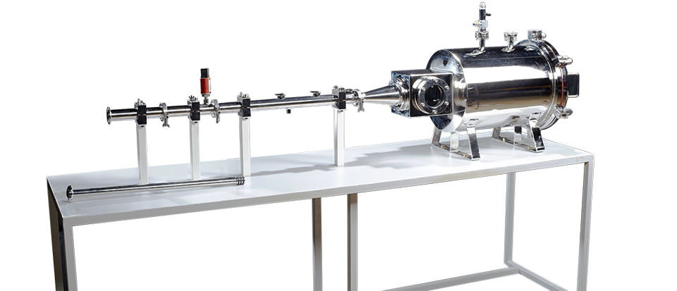
Underwater Shockwave Generator

An underwater electric discharge device has been designed, fabricated and successfully used for creating spherical micro shock waves. The below figure shows the photograph of an underwater shock wave generator. Spherical micro shock waves (few millimetres radius) are generated in water, by instantaneously depositing electrical energy (100 J) between two stainless steel electrodes (1 mm apart) for about 0.35 ms. Peak overpressures up to 100 MPa can be generated for about 10 ms. The water between the electrodes is instantaneously vaporized, creating a tiny vapour bubble. This bubble grows in size and subsequently bursts creating the spherical micro shock wave. The high voltage applied between the electrodes can be varied to generate shock waves of requisite strength. A high-precision mechanical traverse system is used to hold the eppendorf tubes containing any biological samples such as bacterial cells with naked plasmid DNA above the electrodes. The distance between the bottom of the tube and electrodes can be accurately adjusted (least count 0.01 mm) and monitored using a digital encoder. In most of the ongoing experiments, the distance between the sample tube and the electrodes is maintained at ~ 3 mm and the corresponding pressure measured (PVDF Needle Hydrophone, Ms Muller, Germany) inside the test tube was ~ 13.0 MPa.
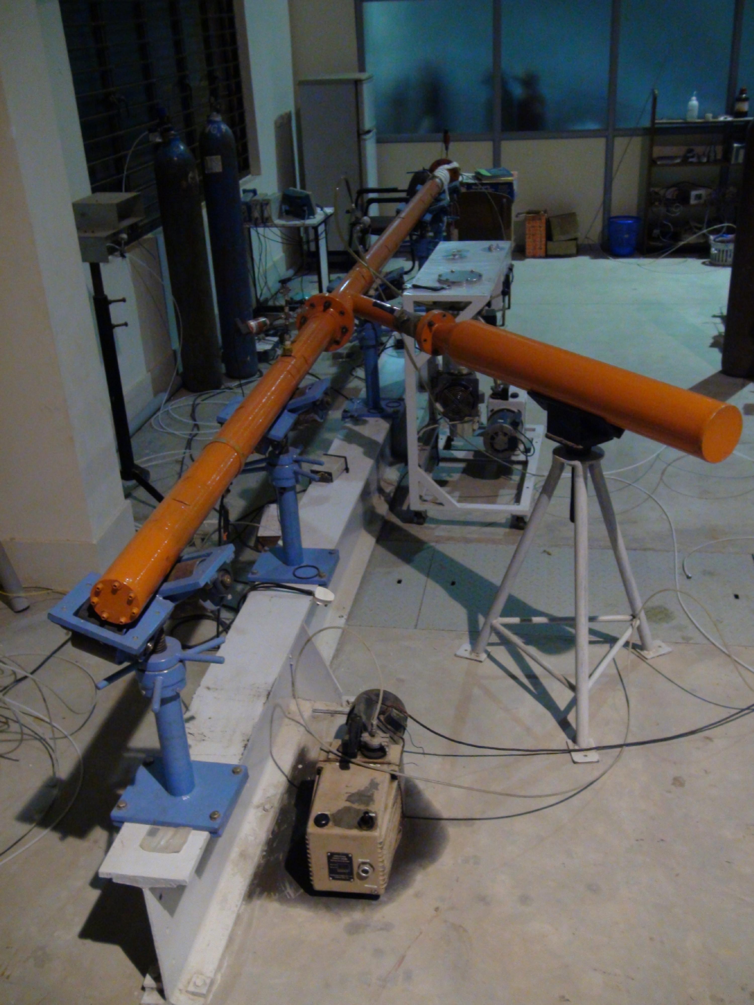
Vertical Shockwave Tube

Shock tubes may also be used to simulate and understand the interaction of a blast wave with a structure. A test plate may be placed at the end of the shock tube and this may then be subjected to blast loading. In order to vary the loading pulse duration, we need to have a provision to vary the driver and driven tube lengths. At LHSR, we have two vertical shock tubes for this purpose, each of 136 mm inner diameter, opening into a safety tank on which these tubes are supported. These tubes have been designed to handle a shock pressure of 100 bar. Two shock tubes were made with an intention to study the effect of multiple point loading on wider samples such as concrete blocks. This facility has the provision to vary the lengths of the driver section (3 tubes of 0.5 m each) and the driven section (one tube of 1.5 m, 3 tubes of 0.6m, 1 tube of 0.5 m, and one tube of 0.39 m). We also have a driver section tube whose length may be varied from 80 mm to 200 mm. The safety tank has provisions to view the deformation of the test plate through five 350 mm viewing windows. To test plates that will be subjected to under-water blast loading, we need to have an easy way to handle liquids and so the tubes were designed to be vertically placed.
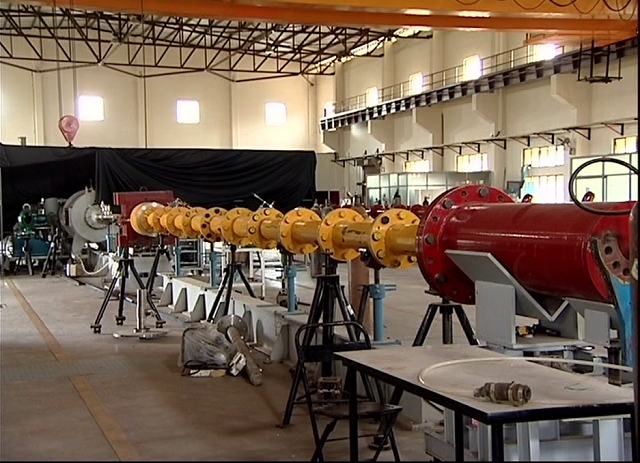
Chemical Shock Tubes
We have established three shock tubes CST1, CST2 AND CST3, shown schematically in the following figure for measuring chemical kinetic rates at high temperatures. The chemical shock tube 1(CST1) is an aluminium tube with inner diameter 50.8 mm and other 2 are stainless steel tubes with inner diameter 39 mm and 50.8 mm respectively. CST 1 and CST 2 are single pulse shock tubes while CST 3 is designed to work for online measurements such as ignition delay and Atomic Resonance Absorption Spectroscopy (ARAS) studies. CST2 and CST3 are provided with optical ports to facilitate absorption and emission spectroscopic studies.
Incorporation of Driver Insert in Chemical TubeA Strategy to achieve the near constant pressure behind Reflected shock Shock tube is an ideal tool to study chemical kinetics at elevated temperature and pressure. It provides near ideal behavior behind reflected shock wave which helps in the measurements of ignition delay times and determination of reaction rates. Any non-ideal effects such as incident shock wave attenuation, boundary layer growth etc. will cause gradual rise in pressure behind reflected shock region in turn result in change in temperature behind reflected shock wave. In order to overcome such problem we have also employed the methodology of putting “driver insert” in driver section in our chemical shock tubes which thereby can counterpart non ideal rise in pressure behind reflected shock. The driver insert acts as sources of expansion waves and provides near ideal behaviour behind reflected shock waves. When the driver insert is employed in shock tube, near ideal performance in reflected shock wave experiment can be achieved.